


The key ingredients you need to be the master chef of your photonic network
Next-generation technologies are bringing unprecedented benefits to optical networks today, but with that can come increased operational complexity. As operators evolve their networks to leverage these benefits, wouldn’t it be great if there was a simple recipe to help ensure successful transformations? Luckily there is.
 The essential ingredients are a programmable optical infrastructure with a flexible-grid reconfigurable photonic layer, analytics and intelligence, all of which are combined with software control and automation. This recipe will enable advanced software applications to eliminate the complexity associated with next-gen flexible technologies and help operators extract the most value from existing network resources.
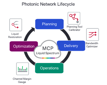
Now you know the ingredients, but where can you find this recipe already made? With Ciena’s Liquid Spectrum applications, that combine these ingredients and are already changing the way network operators engineer, monitor and control the network. Liquid Spectrum leverages Ciena’s Manage, Control, and Plan (MCP) domain controller to unify lifecycle network and service management and online network planning, allowing operators to drive operational efficiency, service agility and automated operations across multi-layer Ciena infrastructure.
Let’s take a closer look at how these advanced software applications enable key benefits for operators at any point of the lifecycle of their optical network, from planning and service delivery to operations and optimization of the network by contrasting the new operating model with Liquid Spectrum, to the current mode of operation.

PLANNING: simplify capacity planning and ensure optimal performance
Today, the planning phase of the photonic network lifecycle starts with some upfront information about the fiber plant, such as the fiber type and fiber length, being fed into a planning tool. When the time comes to light up a wavelength, the operator needs to consult their spreadsheet to determine which wavelengths are used/available in the network, and then use the planning tool to determine the capacity for the type of modem across this path.
The problem with this approach is that optical hardware deployment decisions are made based on upfront link engineering, which is often determined using inaccurate fiber characterization data and worse-case assumptions about the fiber, equipment, patch panels, etc. This approach limits network efficiency and forces operators to operate at suboptimal capacity, leading to unnecessary overbuilds. Additionally, limited visibility into the stability of system margin also means operators are often unaware of system performance degradation until there is a service impact.

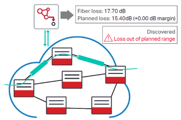 Planning Tool Calibrator eliminates all the manual link engineering and spreadsheet checking processes currently in use today by allowing operators to access actual fiber characterization data for deployed services using real-time data from the network. This accurate fiber characterization information, that includes fiber length and span loss, feeds into planning tools to update planning data for future services, significantly optimizing capacity planning, and providing the ability to act in case of fluctuations. This information enables users to have access to real-time, accurate data for both the existing services and new planned services, which means operators can proactively ensure optimal performance.
DELIVERY: eliminate manual engineering steps and accelerate service turn-up
Now that our network is deployed, it’s time to put some channels on the network and start to deliver services. Today, when operators need to deploy a certain amount of capacity between two points, they manually select the type of wavelength they expect to deploy and perform a link engineering exercise that results in a ‘Pass’ or ‘Fail’ outcome. This requires expert users to run the exercise for all available wavelength capacities. Once the link engineering is complete, users manually determine the maximum channel capacity that can be deployed with acceptable margin for the path in question. This approach was fine, in a world where line optics supported one or two capacity rates and we were dealing with a fixed-grid network. But now, we are dealing with a flexible-grid network in a world where coherent modems support a multitude of settings (such as baud and capacity rates), making this process increasingly complex. Advanced software tools and increased automation are required to enable operators to fully operationalize and realize the benefits associated with a modernized network.
 Bandwidth Optimizer automates the process of selecting the modem modulation format and spectral assignment for a given path. All the operator needs to do is input the total
 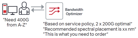 capacity requirements for points A to Z via MCP, and Bandwidth Optimizer outputs the optimal solution. Although this is a very simple process for the user, in the background a built-in PCE (Path Computation Engine) is doing all of the work and provides results that take into account user-defined constraints such as latency, including or excluding transit ROADM nodes/lines and route diversity for channels. The result is a list of optimum configuration options (with associated Bill of Materials) and channel placement, in the most spectrally efficient manner, based on customer-definable margin policies.
OPERATIONS: gain instant visibility into network efficiency and turn-up capacity on-demand
The planning and service delivery stages of the photonic network lifecycle occur in a forecast tolerant fashion – which means that the services delivered are viable even at full-fill end-of-life conditions. Now that we have photonic services in the network, can we determine how these channels are performing relative to what was planned? Is there a way to verify how much margin the channels have at this very 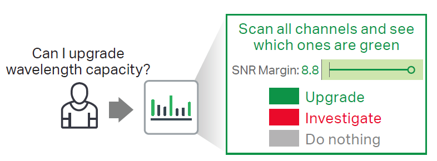 moment? Is more channel capacity possible for a given wavelength? The answers to these questions are available using Channel Margin Gauge (CMG), which provides an instant snapshot of the performance for the active wavelengths in the network.
 Channel Margin Gauge provides an easy-to-read color-coded horizontal bar graph of the SNR operating margin for any active channel. This graph displays the current SNR Margin for a channel in a fixed scale from 0dB (failure point, not enough margin) on the left, to 10dB (lots of margin) on the right. The color of the graph, reflects how the channel is performing in real-time, intuitively letting the user know if the channel is performing as expected, if they need to investigate because margin is lower than expected, or if the channel has plenty of margin making it a capacity upgrade candidate channel.
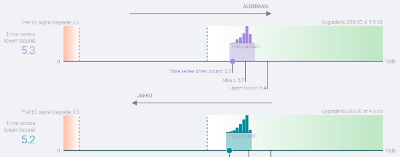
As shown here, with CMG, operators can turn-up capacity on-demand by temporarily borrowing margin available for given channel, by up-shifting the capacity of an upgrade candidate channel.
OPTIMIZATION: real-time, system optimization
The last phase in the lifecycle, leverages analytics and intelligence to drive new levels of system optimization. One example applies to optical restoration of wavelengths, that today can only be completed successfully if the restoration path is viable for the full capacity to be restored and the exact amount of spectrum used in the working path is available on the restoration path.

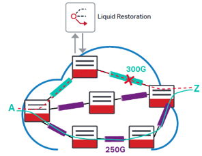 Liquid Restoration leverages user-defined service policies alongside flexible photonic resources to increase service availability versus what is possible today. In contrast to today’s networks, where services would have been dropped or additional hardware would have needed to be deployed, Liquid Restoration flexibly adjusts the transport capacity of deployed coherent optics as needed for operation across any available path in the network.
As operators continue their network evolution journey, it is clear that increased automation of the photonic layer delivers important operator benefits throughout the entire photonic network lifecycle. Ciena’s Liquid Spectrum applications abstract complexity, making it fast and easy for operators to make intelligent decisions based on the current state of the network.