


The benefits of an integrated C&L-band photonic line system
The photonic layer is the foundation for high capacity networks. Whether the network application is to increase connectivity between data centers, deliver bandwidth-intensive content, or to move business applications into the cloud, the photonic layer provides the mechanism to efficiently light the fiber by assigning and routing wavelengths across the optical spectrum. However, today’s photonic layer systems utilize only a portion of the usable spectrum within the fiber, and operators are increasingly looking at expansion into the L-band to increase capacity.
There are a few factors driving the desire for L-band. First, and foremost, is traffic demand. Networks with high bandwidth applications and sustained bandwidth growth are quickly faced with capacity exhaustion. Once existing capacity is consumed, lighting additional fiber pairs is required. If the cost of laying or leasing new fiber is too prohibitive, then alternatives to unlocking additional capacity are needed.
The L-band is one such solution, and it can be used to double the fiber capacity. But, for operators to consider deploying L-band solutions, they must be simple to plan and deploy, and the upgrade to L-band must not impact existing traffic in the C-band.
Building the foundation for a scalable network infrastructure isn’t just about knowing what building blocks to use. It also includes selecting the appropriate architecture and understanding how the pieces fit together, so when it is time to increase capacity, there aren’t any surprises, performance hits, or suboptimal capacity limits.
The historic approach to deploying L-band has drawbacks
Historically, the approach to deploying L-band has been to initially deploy C-band equipment with a C+L-band coupler, and later upgrade to add L-band equipment when needed (Figure 1).
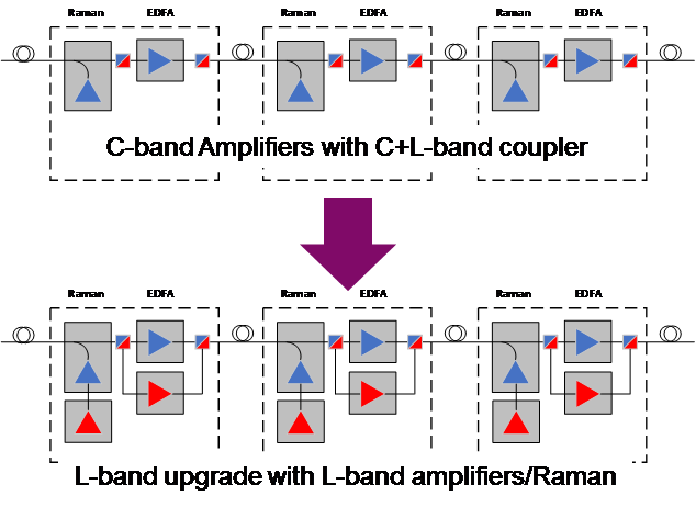
Figure 1: Historical C+L-band upgrade solution
However, this upgrade approach has several drawbacks:
- Revisiting sites: Every site must be revisited to upgrade the Reconfigurable Add-Drop Multiplexers (ROADMs) and in-line amplifiers. This means more operations and technicians required at both nodes and hut locations along the route.
- More cards to manage and spare: Separate C-band and L-band cards result in two times the number of cards to manage and double the footprint at hut locations where space is a premium.
- Scalability limitations: Since the Erbium-doped Fiber Amplifier (EDFA) and Raman amplifier designs can only be optimized for C-band (not both C-band and L-band) initially, the performance can be degraded when upgrading to L-band, resulting in less than double the capacity of a C-band-only system.
- Performance impacts: C+L-band amplifier calibration cannot be performed on networks with in-service C-band channels, resulting in sub-optimal system performance and reduced capacity (Figure 2). Furthermore, the C+L-band coupler requires additional margin day-one to enable an in-service upgrade to L-band which further reduces overall system capacity.
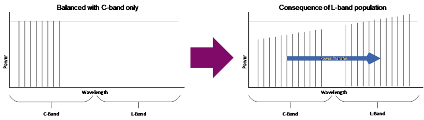
Figure 2: Performance impacts from Stimulated Raman Scattering (SRS) and power transfer for L-band upgrade
Overcoming risks with a day-one optimized C&L-band solution
Ciena’s integrated C&L-band solution on the 6500 Reconfigurable Line System (RLS) is designed with performance and scalability in mind. With the 6500 RLS, network operators deploy, day 1, C&L-band optimized equipment that uses integrated channelized Amplified Spontaneous Emission (ASE) loading to ensure maximum fiber capacity, optimal system performance and guaranteed in-service upgrade. Operators initially deploy integrated C&L-band amplifiers, then when L-band is needed, only the ROADM sites need to be upgraded – no site visits are required for the amplifiers (Figure 3).
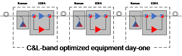
Figure 3: Ciena's optimized C&L-band architecture
The main benefits of Ciena’s integrated C&L-band architecture, include:
- Simplified operations: Does not require site visits to deploy L-band amplifier upgrades at every hut along the route.
- Optimal performance and capacity: Get double the capacity with L-band by optimizing performance day one across both C-band and L-band. This eliminates performance concerns due to interactions between C-band and L-band channels, such as: signal-to-signal induced gain offset, signal-to-signal induced SRS tilt offset, and Raman amplifier gain ripple and gain error. Performance is known and pre-optimized at deployment because C&L-band EDFAs, Raman, and ASE loading are present.
Filling the unused spectrum with ASE maintains full loading conditions on the system, so that system performance can be known and optimized at the time of deployment (Figure 4). This ensures that no additional margin needs to be budgeted for an L-band upgrade, and that the system’s performance will remain consistent across its lifetime, regardless of channel loading conditions – whether the L-band is carrying live traffic or not, the system behaves as if it is fully loaded from day one.
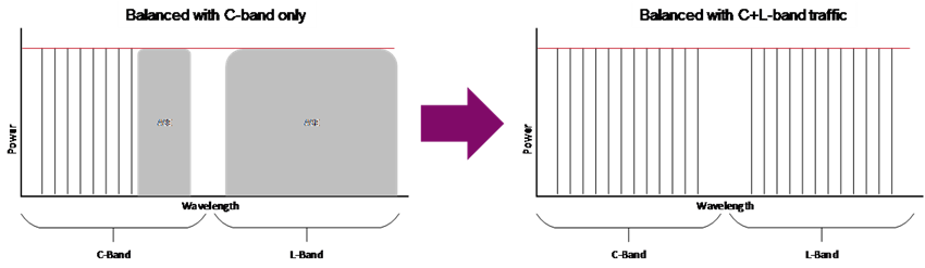
Figure 4: C&L-band optimized solution with ASE loading for optimal performance and capacity
- In-service upgrade: Ciena’s solution with 6500 RLS provides a hitless, in-service upgrade to add L-band.
- Better density at amplifier sites: Reduces space usage at amplifier sites by using the same number of cards for C&L-band as a C-band only amp configuration.
With Ciena’s 6500 RLS, network operators can efficiently scale their networks to meet the most demanding photonic layer requirements with a fully in-service upgradable, optimized C&L-band solution that is optimized to provide maximum performance and capacity, minimize footprint, and improve density.