


What is ROADM?
An Optical Add/Drop Multiplexer (OADM) is a Wavelength Division Multiplexing (WDM) networking device that has access to all wavelengths on a fiber and allows for specific wavelengths to be dropped or added at a location while also allowing other wavelengths to optically pass through the site without requiring termination. OADMs enable wavelength reuse by allowing a wavelength (i.e., wavelength1) to drop from one direction without continuing through the site, so that the same wavelength can also be added to be transported towards the opposite direction. One drawback to basic, fixed OADMs is they generally cannot be modified or reconfigured after deployment, even if traffic volume and patterns need to change. They are also limited to two directions.
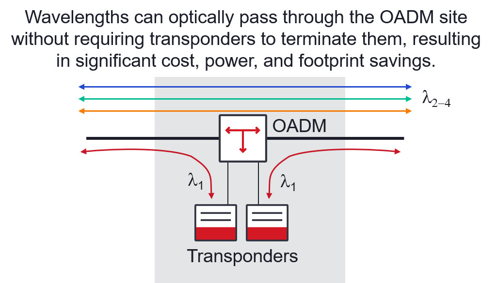
Figure 1. OADM site with optical passthrough
To easily adjust to changing traffic demands, the Reconfigurable Optical Add/Drop Multiplexer (ROADM) was introduced in the early 2000s. ROADMs enable remote configuration (and reconfiguration) of A-Z lightpaths, and support more than two directions at sites for optical mesh-based networking. Like its predecessor the OADM, the ROADM allows individual wavelengths to add and drop at a site, with the added benefit of being able to adjust or change the add/drop vs. pass-through configuration if traffic patterns change.
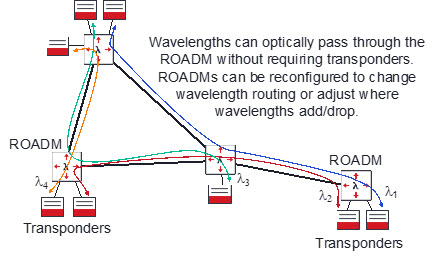
Figure 2. ROADM based networks can be remotely reconfigured if traffic patterns change
At intermediate sites along a wavelength path, the ROADM can redirect wavelengths to the appropriate direction for the next site in the path. This simplifies operations by automating the connections through an intermediate site, much like an automated patch panel, so technicians no longer need to be deployed to perform manual patches to provision a new wavelength or change a wavelength’s path through the network.
Initially, ROADMs utilized fixed-grid Wavelength Selective Switch (WSS) technology that functioned on a specific channel plan and spacing. These ROADMs were often based on either a 50 GHz or 100 GHz fixed grid. Each wavelength added to the network had to fit within this rigid channel spacing in order to pass through the ROADM. However, as coherent technology shifted to higher baud signals with wider channel sizes, wavelengths began to require more space than a fixed-grid 50 GHz or 100 GHz system could provide. Now ROADMs have evolved to support flexible grid, where individual channels can use different channel widths and spacing. This allows modern photonic line systems to take advantage of advancements in coherent technology to increase spectral efficiency and reduce cost, power, and space per bit. Today more than 90 percent of ROADM nodes utilize flexible-grid WSS technology.
ROADM nodes designed with flexible-grid WSS can support different architectures with varying levels of flexibility. The most basic ROADM architecture utilizes fixed filters for add/drop. Other architectures allow for flexibility in wavelength assignment or color, the direction that add/drop wavelengths exit a site, or the ability to freely route wavelengths in any direction without restriction.
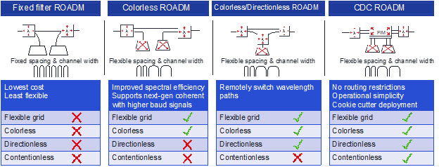
Figure 3. ROADMs support several architectures with varying levels of flexibility
Fixed filter ROADM architecture
The lowest cost but least flexible option is the fixed filter ROADM architecture, which acts as a reconfigurable version of the fixed OADM site. The ROADM enables the ability to adjust which wavelengths are added and dropped, and it can redirect wavelengths that are passing through the site.
This architecture uses a fixed Channel Mux/Demux (CMD). Fixed filters follow a specific channel plan, forcing the network to adhere to a rigid channel spacing, for example 50 GHz, 75 GHz, or 100 GHz spacing. Furthermore, each filter port is fixed to a specific wavelength frequency, so wavelength1 may be connected to port 1 on the filter, but cannot be connected to any other port. Additionally, each filter is directly connected to a specific direction. As a result, when wavelengths are added to the network, they must be connected to the CMD and ROADM that faces the direction they need to go. To deploy wavelengths that require wider spacing in this network, new CMDs are required—and each of these would need to be connected to an available WSS port.
Colorless, also known as Colorless Direct Attach, ROADM architecture
Moving to a colorless ROADM architecture adds flexibility to the wavelength assignment, channel width, and channel spacing through use of a Colorless CMD(CCMD). Colorless capability lets the network support any modern coherent optical technology to realize improvements in capacity, footprint, power, and cost per bit regardless of the coherent technology generation used. Colorless ROADMs also enable a more open, flexible network that can support wavelengths from different vendors. Much like the fixed-filter ROADM, the Colorless Direct Attach (CDA) ROADM is a simple architecture that is easy to scale.
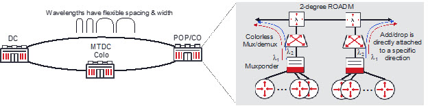
Figure 4. CDA ROADM architecture
The CDA ROADM node can be expanded to connect to new degrees of connectivity or provide additional colorless add/drop. Since the CCMD is directly attached to a specific direction when adding and dropping new wavelengths at a site, they must be connected to the correct direction’s CCMD and ROADM.
Some CDA ROADM architectures also support transponder direct attach, where a transponder can directly attach to a ROADM port without requiring a CCMD. This provides a lower first-in cost for nodes with lower traffic requirements with the tradeoff of consuming ROADM ports for each transponder that is directly attached. Transponder direct attach is a good option for low growth, low volume sites. If traffic requirements dramatically change in the future, a CCMD can be added to provide additional fanout for more add/drop channels.
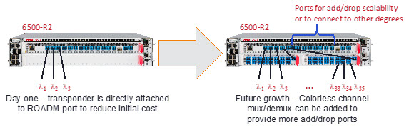
Figure 5. Transponder direct attach for low-growth locations
Colorless, Directionless ROADM architecture
For more add/drop flexibility, a Colorless, Directionless (CD) ROADM may be deployed. Unlike the CDA ROADM where each CCMD is directly attached to a specific direction, the CD ROADM adds additional ROADM equipment to remotely change the direction for each add/drop channel. It also enables the use of any coherent technology and provides colorless add/drop flexibility.
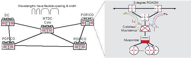
Figure 6. CD ROADM architecture
The directionless functionality adds the benefit of remotely switching the direction of add/drop wavelengths. This can be used to enable optical layer reconfiguration and restoration. If there is a failure, an optical control plane can redirect add/drop channels from one direction out of a node to a different, alternate direction. However, this architecture does not allow for full wavelength routing flexibility as it does not eliminate wavelength contention when multiple versions of the same color wavelength are being added at a single location to be sent in different directions. This architecture only allows for a single instance of each color wavelength to add/drop at each location.
Colorless, Directionless, Contentionless ROADM architecture
For full wavelength routing flexibility, a Colorless, Directionless, Contentionless (CDC) ROADM architecture is required. The contentionless capability of a CDC ROADM allows the same wavelength to add/drop off of a single CCMD for different directions. In other words, port 1 on the CCMD could be wavelength1 for the east direction, and port 2 on the CCMD could be wavelength1 (i.e., same frequency) for the west direction. This means that a CDC ROADM node has no restrictions or limitations with respect to wavelength assignment or routing, and it can be used for photonic layer network optimization and dynamic re-routing of wavelengths for traffic restoration.
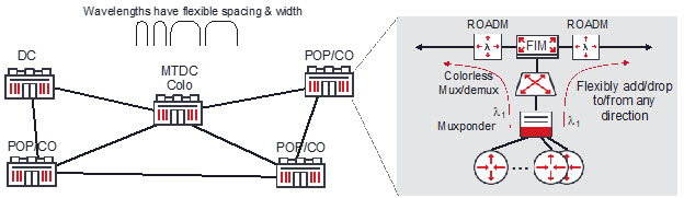
Figure 7. CDC ROADM architecture
The CDC ROADM node retains all of the benefits of the other flexible-grid ROADM types, such as the ability to use any coherent technology to gain improvements in spectral efficiency and cost per bit. It provides flexible channel width and spacing and grants directionless capability without wavelength blocking restrictions. CDC ROADM nodes require more sophisticated WSS equipment than other options which increases the overall cost, but they also provide the most flexible and programmable ROADM architecture available today. This flexibility enables network providers to quickly respond to unpredictable traffic demands. CDC ROADM also enables widescale, cookie-cutter deployments because its full wavelength routing flexibility eliminates the detailed wavelength assignment and routing pre-planning that is typically required when deploying an optical line system.
Modern ROADM networks can be used to automate the configuration of add/drop ports at a site and easily scale to accommodate new fiber routes. Depending on the architecture, ROADMs can dramatically reduce the amount of wavelength routing and assignment pre-planning that is required for WDM networks. ROADMs can be used in ring or mesh architectures. With the ability to re-route wavelength paths across the network, ROADMs can be used to provide optical layer restoration. Flexible-grid ROADMs future-proof the photonic layer, ensuring that it is compatible with any new coherent technology regardless of the baud being used. Flexible-grid channel spacing works with next-gen coherent modems for high-rate signals, including 800G, to achieve maximum spectral efficiency for WDM applications, and opens the line system to provide the flexibility to use any vendor’s coherent optics.
With WaveLogicä Photonics, Ciena offers a full range of photonic layer architectures on the 6500 and 6500 RLS platforms from fixed, passive filters to flexible-grid ROADMs. Intelligent Layer 0 control plane simplifies operations via automated inventory, faster service and wavelength provisioning, and increased network availability. This allows network providers to offer a wide range of service-level guarantees and have as much control over wavelength routing as desired.
With Ciena’s WaveLogic Photonics, network providers can increase line system openness and programmability. The network can be managed through open APIs using standard data models or with Ciena’s Manage, Control and Plan (MCP) domain controller. Ciena’s line systems accept wavelengths from any vendor’s coherent optics, including pluggables and transponders, giving network providers more flexibility and choice. Ciena’s Liquid Spectrum™ apps leverage WaveLogic Photonics’ highly instrumented and programmable line systems, and combine them with advanced software applications. This allows network providers to tune, control, and adjust optical capacity in real time, enabling access to new revenue streams and the ability to more fully monetize existing assets.