


How I built my own mobile cell tower
Al Lounsbury is based in Ciena’s Ottawa Campus and is part of our Digital Marketing team.
Do you have a special place where you love to relax and unwind, but can’t because of a lack of cell phone or mobile data coverage? Or maybe you’re having issues getting good cell reception in your own home where your second office is located. For most people, the answer to these problems is to ‘just deal with it’ or try switching providers. But as an avid do-it-yourselfer and an engineer, that wasn’t my style. My solution was to build my own cell tower.
In my case, I have a cabin in Northern Ontario. It’s beautiful and peaceful there, but the nearest grocery store is 30 minutes away in a town with a population of less than 1,000 people. Cell coverage is spotty at best. If I’m on top of a hill on a clear day, I might be able to pull in one bar on my mobile. In fact, many renters in the area take a daily walk to the top of a nearby hill just to receive their text messages and emails.
So my engineering challenge was to figure out how to obtain great mobile coverage at my cabin, allowing me the occasional Friday work day there versus being in the office cube. Here’s how I did it using common materials you can find online or at your local home improvement store.
Researching Your Needs
Step 1 in the process is to find the nearest cell tower to your location and figure out on what frequency band the tower operates on. Most 3G/4G systems operate in either the 800 (824 to 894) MHz or 1.9 (1.85 to 1.99) GHz band. The 800 MHz band will have a greater range than the 1.9 GHz band due to atmospheric attenuation, hence many carriers prefer the 800 MHz band for greater area coverage.
For my fellow Canadians, here’s a great website which maps all the towers in Canada for multiple carriers and provides details, including their frequency band. You can also check with your mobile carrier and ask the technical support department for the nearest tower and its frequency band. Additionally, you can search your phone’s app store for “cell signal,” and multiple apps will pop up that can help. On Android, I use the Open Signal app, which provides the direction of the nearest and strongest tower. In my case, the nearest Rogers cell tower is located in Bon Echo Provincial Park and operating at 850 MHz. With my research done, it was time to move on to gearing up for the build.
Buying the Components You Need
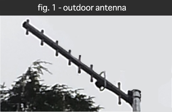
Your basic list of required components consists of a tower, an outdoor antenna, an indoor antenna, a bi-directional amplifier, and RF cables. For the best performance, make sure that your outdoor antenna is highly directional, essentially a narrow, laser-like beam that points directly to the nearest cell tower. By keeping the antenna highly focused, we ensure that all the signal power is directed at our target tower and not sprayed over a wide area. This is referred to as antenna gain and the higher the gain number the more focused the antenna power will be. The antenna I used is a 13 dbi gain 800 MHz Yagi antenna (fig. 1), found here.
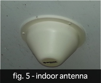
 Next up is our indoor antenna. We want to maximize indoor coverage hence the gain number will be much lower, as we aim wide, not far. Also, to keep household peace with the lady of the house, installing an ugly antenna on the wall was “not” an option for me, but luckily a ceiling mount was. By using a dual polarized (vertical & horizontal) ceiling mount antenna, you can provide 360-degree coverage around the antenna with a vertical beam width of 150 degrees down from the antenna to the floor. The one I used (fig. 5, Part #301123) can be found here.
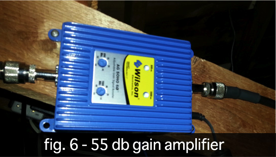
With both antennas in hand, you’ll need to pick out your bi-directional booster. With your booster, it’s all about GAIN and ensuring the gain can be adjusted accordingly. In my case, I picked up a 55 db gain amplifier (fig. 6, here). This worked perfectly and took my cabin from no coverage to 4-5 bars of coverage in any weather condition, including SNOW! That said, if the budget allows for a higher gain amplifier, go for it. The higher gain amplifier will provide better coverage, including the ability to drive more than one indoor antenna if a wider indoor coverage area is needed.
We now have all the major components and just need to connect everything together with good “low loss” RF cable since we do not want to waste precious signal power with leaky high loss RF cables. A good low loss 20-foot cable should have a loss of 1 db or less. And yes, a single db is significant. To put in perspective, a 3 db loss means that the signal power has been reduced by FIFTY percent…yes half! So every db counts, and ensuring one uses ultra-low loss cables is highly recommended if maximum coverage (gain) is needed.
Building the Tower
With our components in hand, we need to identify our antenna placement locations. As the outdoor antenna is highly directional and the indoor antenna is basically focused straight down below the outdoor antenna, we need to ensure that the outdoor antenna does not point over the indoor antenna, allowing for roughly 15 feet of vertical separation. These separation requirements get much stricter if non-directional outdoor antennas are used with panel indoor antennas. In these cases, 20 feet vertical and 20 feet horizontal separation could be required to prevent RF feedback. This feedback is similar to audio feedback that occurs when a microphone (inside antenna) gets too close to the output speakers (outdoor antenna). If feedback does occur, your amplifier will shut down, so make sure that you space each antenna carefully.
The tower itself is a simple thing to build. And for me, a trip to Home Depot was all that was required. I used 1 ¼” galvanized pipe in 6 foot sections for the tower (fig. 3) and a shorter 4 foot 2” pipe (fig. 2) to anchor into the ground. Although steel pipe would be cheaper, it also requires painting to ensure it does not rust, so I rejected that option.
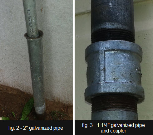 You’ll need to drive the 2” pipe into the ground with a sledgehammer or the back of an axe to allow the 1 ¼” pipe to slide into it as shown in figure 2. Space the pipe away from the home’s foundation about the same distance as the upper strap you’ll use to secure the pole at the roof line. This will help ensure your tower is vertical and not leaning one way or the other. Having a directional antenna pointing 10 degrees down or up would not be good.
After securing your tower, attach the Yagi antenna to the 1 ¼” pole using the mounting hardware provided with the antenna. Don’t forget to attach your ultra-low loss cable and use electrical tape to strap the cable to the pole so wind does not cause the cable to wear.
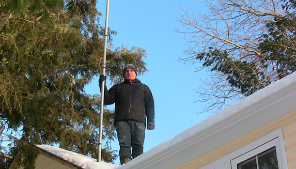
 To get the height you need, simply add additional 6’ pole sections from the bottom up using couplers (shown in figure 3) to push the antenna higher while taping down the cable on the side of the pole. By adding sections to the bottom at ground level, you keep yourself off the roof. In my case I have five 6’ sections holding up the antenna for a total height from the ground of 30’. Use galvanized strapping (fig. 4) at the roofline to secure the pole into position so it does not fall or sway to one side or the other.
At the roofline, find a place (soffit vent or drill a hole) to feed the antenna cable into your attic/home and point the antenna roughly in the direction of the nearest cell tower. We’ll fine-tune the placement later.
For the indoor antenna location, this is a good time to consult with your spouse, as I did with the lady of my cabin. The only placement requirements are that it cannot be in the same vertical line as the outdoor antenna and should be near the indoor area where the coverage is needed most. So the winning location for me was on the ceiling by the cabin’s entrance as shown in figure 5.
 Now it’s time to head up to the attic to mount the amplifier and connect all the RF cables. The amplifier should be placed in a convenient easy to access location in case maintenance is ever needed. I placed mine on a rafter that is right beside the attic hatch as shown in figure 6.
In order to minimize power consumption, I turned the gain of the 1.9 GHz band as low as possible since I didn’t need any 1.9 GHz power. I then maximized the gain of the 850 MHz band. In your case the opposite may be true, but you should only need one band maxed out.
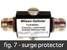
You’re almost done, but I do have a couple of final recommendations. First, it’s a good idea to install lightning surge protection, in figure 7, as this is an electrically conductive metal pole that reaches high up into the air. This surge protector gets installed on the outside antenna side of the amplifier and needs a good grounding wire on it to conduct any lighting surges to the ground, safely away from the amplifier. It’s important to know that anytime a lighting strike is “near” the antenna that it will produce a surge. Surge protection is a great investment and it only introduces a 0.2 db loss. Protecting your investment properly is highly recommended.
Secondly, consider installing an Uninterruptable Power Supply (UPS) on the amplifier so you can continue to have cell coverage even when there is a power failure. There is nothing like streaming a good movie when the power is out, and having a phone available for emergency calls is valuable.
 With all the RF cables firmly connected, it’s time to power up the amplifier. The amplifier’s lights will initially start blinking green, and in 15 minutes they should stay solid if all is working correctly. If you don’t get solid green lights, consult the amplifier’s troubleshooting guide, but for me, the first attempt gave me all green lights!
Once powered up, it’s time for the final step: aligning the antenna for maximum reception. Although the bars on a cell phone can be useful for casually gauging reception, they lack accuracy and only update once every 30 seconds to 2 minutes depending on the brand. However, every mobile phone has a hidden test mode that will update the signal strength every second. Many of these codes can be found from searching on Google for “<insert mobile brand name> test mode codes”. You’ll be looking for the dial sequence to input in order to access the test mode.
 After entering your code, select UMTS, debug, and basic. The key numbers are RSCP (received strength coded power) and Ec/lo which is a ratio of good energy over bad energy akin to a signal to noise ratio. Getting an Ec/lo of -10db and higher (meaning less negative) is ideal. While watching the RSCP number, turn the antenna a couple of degrees and then wait for the numbers to update. There will be a place where RSCP and Ec/lo maximize themselves, which represents your optimal direction. At this point, you’re done!
By now your remote location should have awesome 3G/4G cell and data coverage, enabling you to leverage some of today’s technological niceties. For example, I can now control and monitor the heating in my cabin, right from my cell phone. As I drive up to the cabin in winter (6 months in Canada), I bring up the app on my phone and turn the heat on so it’s nice and cozy when I arrive. There are lots of advantages to having a stable data signal that we could go into, but of course, that is another blog entry all by itself.
Have any questions on how I did it? Just ask in the comments box below.
[Before beginning any project to boost your wireless signal as Al describes above, be sure to ask the manufacturer of the cellular amplifier about local regulations for both your wireless provider and your local area. For example, in the U.S. the FCC recently adopted rules to ensure the reliability of individual cellular networks by having people operating cellular signal boosters register them with their mobile provider. No such rules exist in Canada at the time this was published.]